
Analysis of Catalytic Combustion Equipment Ignition Failure Causes – From Principles to Troubleshoot
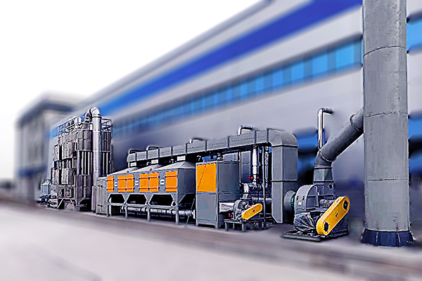
Catalytic combustion equipment is a widely adopted solution for volatile organic compounds (VOCs) treatment in industries ranging from coating and printing to chemical manufacturing. However, operators occasionally face a frustrating issue: the system fails to ignite properly. Ignition failure not only halts production but also compromises environmental compliance. This article provides a systematic analysis of ignition failure causes – moving from fundamental principles to practical, stepwise troubleshooting – helping you restore your RCO catalytic combustion equipment reliably and safely.
1. How Catalytic Combustion Ignition Works – A Brief Principle Review
Before diagnosing ignition failures, understanding the normal ignition sequence is essential. Typical catalytic combustion systems (including RCO and direct catalytic oxidizers) use an electrical heater or gas burner to raise the catalyst bed inlet temperature to the light-off temperature (usually 250–350°C, depending on catalyst type). Once the catalyst reaches activation temperature, VOCs oxidize exothermically, and the system becomes self-sustaining. Ignition failure occurs when the system cannot achieve or maintain this light-off temperature within the allowed time.
2. Primary Causes of Catalytic Combustion Ignition Failure
Based on field experience from Zhengzhou Puhua Technology – a manufacturer specializing in dust removal, desulfurization, denitrification, VOCs treatment, pneumatic conveying, and wastewater treatment equipment – most ignition failures fall into five categories.
Heating element or burner malfunction – electric heaters with broken circuits, gas burner flame failure, or thermocouple faults.
Catalyst deactivation or poisoning – sulfur, chlorine, or particulate matter covering active sites.
Inadequate VOC concentration or flow instability – too low combustibles to sustain exothermic reaction.
Temperature sensor errors – false readings causing premature shutdown before light-off.
Safety interlock activation – purge time incomplete, pressure differential out of range, or over-temperature protection engaged.
3. Systematic Troubleshooting Workflow for RCO Catalytic Combustion Equipment
Follow this logical sequence to identify the root cause efficiently. Always prioritize safety – lockout/tagout electrical and fuel sources before inspection.
Step 1 – Verify pre-start conditions
Check main power supply and control voltage (e.g., 24VDC or 220VAC).
Confirm gas pressure (if using auxiliary burner) is within manufacturer’s specified range.
Ensure all safety doors and access panels are closed – limit switches must be engaged.
Step 2 – Inspect heating source
For electric heaters: Measure continuity across heating elements. A common failure is open-circuit elements after prolonged use.
For gas burners: Check flame rod signal, ignition spark, and gas valves. Clean flame sensor if coated with soot.
Step 3 – Evaluate temperature sensors and controllers
Compare thermocouple or RTD readings with a calibrated reference thermometer at ambient and moderate heat.
Look for wiring corrosion or loose connections, especially near the combustion chamber (high thermal stress zone).
Step 4 – Assess catalyst condition
Measure pressure drop across the catalyst bed. A sudden increase suggests blockage or fouling.
Inspect catalyst modules for color changes (e.g., white sulfate deposits or black carbon masking).
If possible, perform a simple light-off test using a known VOC (e.g., isopropanol) under controlled conditions.
Step 5 – Review system interlock logics
Check the pre-purge timer – insufficient purge time prevents ignition per safety standards.
Inspect differential pressure switches (e.g., fan proving switch, filter clogging switch).
4. Common vs. Uncommon Failure Causes – A Quick Reference Table
| Failure Category | Common Causes (80% of cases) | Less Common Causes |
|---|---|---|
| Heating system | Broken heater element, gas valve closed, flame sensor dirty | Damaged ignition transformer, gas regulator failure |
| Catalyst | Thermal aging, particulate blinding, sulfur poisoning | Halogen poisoning (e.g., chlorine, fluorine), mechanical cracking |
| Instrumentation | Thermocouple drift, loose wire, controller setpoint error | PLC output module failure, analog input card fault |
| Process | Low inlet VOC concentration (< 500 mg/m³), large flow fluctuations | Condensation in ductwork, wrong VOC species (e.g., refractory compounds) |
| Safety interlocks | Pre-purge incomplete, high temperature limit triggered, airflow proving switch stuck | Emergency stop pushbutton damaged, watchdog timer expired |
5. Preventive Measures to Avoid Recurring Ignition Failures
An effective preventive maintenance program dramatically reduces unplanned downtime. Consider these measures for your VOCs treatment equipment.
Weekly: Visual inspection of heating elements (for discoloration or cracks), verify temperature readings against a portable thermometer, clean flame sensor (gas burners).
Monthly: Measure catalyst bed pressure drop, record pre- and post-catalyst temperatures to monitor thermal performance, test all safety interlocks manually.
Quarterly: Perform catalyst activity check using a portable VOC analyzer, inspect and tighten all electrical connections in the control panel, calibrate thermocouples.
Annually: Consider catalyst regeneration or replacement if light-off temperature has risen more than 40°C above baseline, and fully service burner assembly.
Additionally, maintaining stable inlet VOC concentration – using buffer tanks or dilution control – minimizes thermal shock and prevents repeated ignition cycling.
6. When to Call a Professional vs. In-House Repair
While operators can handle many checks (sensor verification, heater continuity, pressure switch testing), certain situations require specialized expertise:
Catalyst removal and laboratory analysis (for poisoning identification).
Gas burner combustion tuning – improper adjustment creates carbon monoxide or unburned fuel hazards.
Control logic reprogramming or PLC troubleshooting.
Zhengzhou Puhua Technology provides technical support for its RCO catalytic combustion units, RTO equipment, and VOCs treatment systems. Our product line includes bag filters, desulfurization towers, denitrification equipment, UV photo-oxidation units, pulse jet dust collectors, mobile dust collectors, ultra-low emission systems, and wastewater treatment equipment. We recommend consulting original equipment guidelines before major disassembly.
7. Real-World Case Example: Solving a Persistent Ignition Failure
A printing plant using an RCO system experienced ignition failure three times per month. The fault code indicated "flame loss during start sequence." The in-house team replaced the flame sensor twice without success. Upon deeper investigation, Zhengzhou Puhua Technology's service engineer found:
The gas pressure regulator was oversized, causing pressure spikes above the burner's maximum rating – the safety gas valve would momentarily shut.
Additionally, the combustion air damper actuator had a 2-second lag, disrupting the air-fuel ratio during ignition.
Solutions: Replaced with correctly sized regulator, recalibrated damper actuator timing, and added a pressure snubber to the gas pressure switch. Ignition reliability improved to 99.9% over the next six months. This case demonstrates that sometimes the root cause lies outside the obvious components.
Conclusion
Catalytic combustion ignition failure is rarely a single mystery – it is a solvable problem using structured thinking from principle to field checks. Start with pre-start conditions, verify the heating source and sensors, evaluate catalyst health, and review safety interlocks. Regular preventive maintenance and keeping detailed logs of temperature profiles and pressure drops will help you catch issues before they cause shutdowns. For complex cases, especially those involving catalyst deactivation or burner control systems, do not hesitate to involve the equipment manufacturer’s technical team.
If you operate RCO catalytic combustion equipment or any VOCs abatement system from Zhengzhou Puhua Technology, our technical documentation and after-sales support are available to help you restore normal operation quickly and safely.
Related Articles
-
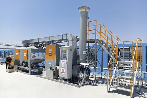
Zeolite Fixed Bed+Catalytic Combustion Equipment (RCO)
[list:visits]
-
Resin desorption+condensation recovery equipment
[list:visits]
-
Cooking oil fume purifier
[list:visits]
Subscribe to Our Newsletter
Stay updated with the latest news and insights from Puhua Tech.